INTRODUCTION:
This web page deals with FNR geometrical constraints imposed by the fuel bundle design. This web page assumes that (3 / 8) inch OD fuel tubes are located on a X = (9 / 16) inch square grid where the value of X is determined on the web page titled: FNR Reactivity by tabulating the FNR reactivity as a function of X.
FNR PLAN VIEW:
The following FNR geometrical calculations are based on a FNR with a target rated thermal power of 1000 MWt. The following diagram shows the plan view of the fuel bundle array.
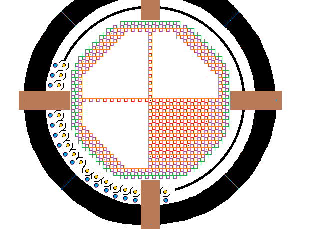
A FNR consists of central active fuel bundles surrounded by passive fuel bundles and cooling fuel bundles which in turn are surrounded by the FNR Skirt with its gadolinium layer and then a ~ 3 m wide liquid sodium guard band. Within the guard band are 48 intermediate heat exchange bundles. The sodium pool walls are 2 m thick and are filled with insulating brick with an average density of about 1.4 g / cm^3and with a 50% fill factor. In the above diagram only one quadrant of fuel bundles is fully detailed.
The active movable square fuel bundles are shown in red. The passive fixed square fuel bundles are shown in purple. The cooling bundles are shown in green. For structural stability the diagonal fuel bundle assembly faces are composed of fixed octagonal fuel bundles, except at 8 clipped corners. A shaped 6 m high perforated steel skirt covered on one side with sheet gadolinium surrounds the assembly of fuel bundles at the same elevation as the fixed fuel bundles. The skirt has eight straight sections each of which is fastened to two 45 degree corner posts.
FNR MOVABLE FUEL BUNDLE DIMENSIONS:
The dimensions of the tubed portion of a movable fuel bundle excluding the shroud thickness, fabrication tolerance allowance, thermal expansion allowance and swelling allowance are:
[17 X (9 / 16)] inches wide X [17 X (9 / 16)] inches long X 6 m tall.
Surrounding the movable tube bundle is a band (9/ 16) inch wide that must accommodate one shroud thickness, fabrication tolerance allowance, thermal expansion allowance and swelling allowance, for a total width allowance of:
19 (9 / 16) inch
= 10.6875 inch.
FNR FIXED FUEL BUNDLE DIMENSIONS:
The external dimensions of the tubed portion of a fixed fuel bundle excluding the shroud thickness, fabrication tolerance allowance, thermal expansion allowance and swelling allowance are:
[21 X (9 / 16)] inches wide X [21 X (9 / 16)] inches long X 6 m tall.
Surrounding the fixed fuel bundle is a band (9 / 16) inch wide that must accommodate one
shroud thickness, fabrication tolerance allowance, thermal expansion allowance and swelling allowance, for a total width allowance of 23(9 / 16) inch = 12.9375 inch.
FNR FUEL BUNDLE PAIR:
Hence the distance allowance for adjacent movable and fixed fuel bundles is:
10.6875 inch + 12.9375 inch
= 23.625 inch
= 0.600075 m
FUEL BUNDLE SWELLING ALLOWANCE:
Each fuel tube bundle has a (9 / 16) inch thick provision all the way around for the shroud thickness, fabrication tolerance allowance, differential thermal expansion allowance and swelling allowance. From the web page titled: FNR Fuel Bundle the shroud plate thickness is:
3 / 16 inch.
Hence, even with perfect fuel bundle fabrication, the maximum possible fuel bundle swelling allowance is:
{[4(9 / 16) inch - 4(3 / 16) inch]} / {[(18 + 22) X (9 / 16) inch] } X 100%
= {4(6 / 16)inch / (40 (9 / 16))} X 100%
= (24 / 360) X 100%
= 6.67%
This fraction has to include the swelling allowance, the fabrication error allowance and the thermal expansion allowance.
If the shroud plate thickness is reduced to (1 / 8) inch the maximum swelling allowance becomes:
{4(9 / 16) inch - (4 (1 / 8) inch} / (40 (9/ 16) inch X 100%
= {(28 / 16) inch /40(9 / 16) inch}X 100%
= (28 / 360) X 100%
= 7.78%
Fortunately thermal expansion is mostly cancelled by thermal expansion of the open steel lattice. In the worst case there might be a thermal differential expansion of:
(10^-5 / deg C) X 500 deg C = 5 X 10^-3
= 0.5%
In summary, to prevent jamming of movable fuel bundles against swollen fixed fuel bundles the fuel bundles must be replaced and reprocessed when the HT9 linear swelling reaches the swelling limit, regardless of its contained Pu or fission product fractions.
FIXED FUEL BUNDLE MAXIMUM DIAGONAL LENGTH:
Neglecting the corner clips the maximum diagonal width of the tubed portion of a a fixed fuel bundle is given by:
23 X (9 / 16) inch X (2)^0.5
= 18.296 inch
Hence the fuel bundle transfer airlock should be made from 20 to 24 inch OD pipe.
MOVABLE FUEL BUNDLE TUBE COUNT:
Three fuel tube positions are lost at each corner to make space for corner girders. Thus each movable fuel bundle shroud potentially contains:
[(17 X 17) - 4 (3)] = 277 fuel tubes.
However, an additional 29 fuel bundles are lost due to the presence of fuel bundle diagonal reinforcement plates, leaving a net of:
277 - 29 = 248 fuel tubes per movable bundle.
FIXED FUEL BUNDLE TUBE COUNT:
The dimensions of a fixed fuel bundle excluding shroud thickness, tolerance allowance and thermal expansion allowance are:
[21 X (9 / 16)] inches face to face X [21 X (9 / 16)] inches face to face X 6 m tall. Eight fuel bundle positions are lost at each corner. Each fixed fuel bundle shoud contains:
[(21 X 21) - 4(8)] = 409 fuel tube positions.
However, an additional 33 fuel tube positions are lost to diagonal fuel bundle reinforcement members leaving a net of:
409 -33 = 376 fuel tubes per fixed fuel bundle.
In order to achieve both good liquid sodium natural circulation, which requires fuel tubes on a square grid, and good horizontal mechanical stability, alternate smaller movable and larger fixed fuel bundles is used. The maximum face to face size allocation for the fixed fuel bundles is set at:
23 X (9 / 16) inch = 12.9375 inches
by transportation weight constraints. The movable fuel bundles are made as large as practical:
19 X (9 / 16) inch = 10.6875 inches face to face
with respect to the fixed bundles to achieve acceptable fuel bundle assembly structural strength and acceptable modulation of average core zone fissile fuel concentration. These dimensions result in a linear center to center spacing of:
[12.9375 inch + 10.6875 inch = 23.625 inch
= 23.625 inch X .0254 m / inch = 0.6000 m.
This dimension permits a scale plan view diagram in m rather than inches.
The above diagram was prepared using a scale of:
14 squares = 0.6000 m
On the above diagram the ratio of the small fuel bundle width to the larger fuel bundle width is not exactly correct but it is close enough for diagramatic purposes.
FLOATING SPHERES:
Note that the allocated center to center distance between indicator tubes is 23.625inches. The Indicator Tube OD is 8.625 inch.
That allows for spacing spherical floats, each with a diameter of up to:
(23.625 inch - 8.625 inch) = 15.000 inch
Hence buoyant spheres with a nominal outside diameter of < 15 inches would be suitable.
ASSEMBLY OF FUEL BUNDLES:
The fuel bundle geometry starts as a 45 bundle X 45 bundle square. The straight horizontal and vertical faces are each 21 bundles long. Hence each of the cut off corners of an isosoles triangle is:
(45 - 21) / 2 = 12
bundle positions to a side. Hence the number of movable fuel bundle positions in each cut off corner is:
12 + 10 + 8 + 6 + 4 + 2 = 42
and the number of fixed fuel bundle positions in each cut off corner is:
11 + 9 + 7 + 5 + 3 + 1 = 36
so the number of fuel bundle positions per cut off corner is:
42 + 36 = 78.
The result is an octagon. In addition two fixed and one movable fuel bundle are clipped of each of 8 octagon corners to avoid clashing with neighbouring intermediate heat exchange bundles.
Hence the total number of fuel bundle positions in the total fuel bundle array is:
45^2 - 4 (78) - 8(3) = 2025 - 312 - 24 = 1689 fuel bundle positions
A physical count shows that there are 464 active movable fuel bundles and 481 active fixed fuel bundles.
Thus the total number of active fuel tubes per reactor is:
(481 active fixed bundles X 376 tubes / fixed bundle)
+ (464 active movable bundles X 248 tubes / movable bundle)
= 180,856 active tubes + 115,072 active tubes
= 295,928 active fuel tubes / reactor
Each fuel tube provides a flowing sodium cross sectional area of:
[(9 / 16) inch]^2 - Pi [(3 / 16) inch]^2
= (81 / 256) inch^2 - Pi (9 / 256) inch^2
= .2059596 inch^2
= 1.328769 X 10^-4 m^2
Hence the total active fuel bundle flowing sodium cross sectional area is:
1.328769 X 10^-4 m^2 / fuel tube X 295,928 active fuel tubes
= 39.322 m^2
A physical count shows that there are:
4 X 57 = 228 cooling fuel bundle positions, of which 112 are for fixed fuel bundles and 116 are for movable fuel bundles.
Hence the number of passive fuel bundles is:
1689 - 464 - 481 - 228 = 516 passive fuel bundles.
The minimum number of times through cooling residency required to cool all the active fuel bundles in a reactor is the larger of:
(464 M / 116 M) = 4.0
and
(481 F / 112 F) = 4.295
which imples at least 5 fuel bundle cooling cycles per complete fuel cycle.
Thus if the period of a fuel cycle is 30 years, there should be a planned reactor shutdown every 6 years for partial fuel bundle exchange and fuel bundle shuffling.
To minimize the liquid sodium requirement the assembly of fuel bundles is chosen to be close to a regular octagon so that it will fit snugly within a circular liquid sodium tank wall. Before octagon corner clipping the octagon straight faces consist of 11 octagonal fuel bundles separated by 10 square fuel bundles. The length of a straight side measured between the centers of the end bundles is:
10 X 42 X (9 / 16) inch = 236.25 inch = 6.000 m.
Measured between the ends of these fuel bundles the straight face length is:
236.25 inch + 23(9 / 16) inch = 249.1875 inch = 6.3293625 m
The octagon angled faces each consist of 13 corner connected octagonal fixed fuel bundles. Straight and diagonal face fuel bundles are shared at corners.
Measured along a diagonal through octagonal fuel bundles, the allocated center to center distance between adjacent octagonal fuel bundles is:
(2^0.5) X [23 X (9 / 16) inch]
= 18.2963 inch = 0.46473 m
Measured from octagonal fuel bundle center to octagonal fuel bundle center the allocated length of a diagonal face is:
12 X 18.2963 inch
= 219.5556 inch = 5.5767 m
which is less than would be the case for an ideal regular octagon.
The fuel bundle positions are a subset of a theoretial array 45 bundles X 45 bundles. There is a fixed bundle at each corner of the theoretical array and there is a fixed bundle at the center of the array.
Measured from fixed fuel bundle center to fixed fuel bundle center the allocated horizontal face to horizontal face distance of the
entire assembly of fuel bundles is:
[22] X [(42 X (9 / 16) inch] = 519.75 inch = 13.20165 m
Measured from the outside edges of the octagonal fuel bundles the fuel bundle assembly horizontal face to horizontal face distance is:
519.75 + [23 X (9 / 16) inch] = 532.6875 inch
= 532.6875 inch X .0254 m / inch
= 13.530 m
GUARD BAND WIDTH:
The intermediate heat exchange bundles are located at an elevation above the top of the fuel tubes, so that the sodium guard band extends under the intermediate heat exchange bundles. The reactor sodium pool is 20 m inside diameter which provides a neutron absorbing guard band about 3 m wide around the perimeter of the fuel bundle assembly. The sodium pool liner is further protected by a sheet gadolinium skirt. The intermediate heat exchange bundles are protected from neutrons originating in the core fuel via a very long diagonal path through the fuel blanket.
Note that the cost of the reactor enclosure roof and the reactor service gantry crane increase rapidly with increasing sodium pool diameter, so larger fuel assembly diameters may be uneconomic.
From a structural component transportation perspective it is advantageous to keep most of the steel beams that support the reactor, its enclosure roof and the gantry crane less than 16 m long. This restriction allows the use of a liquid sodium pool that has an inside diameter of 20 m and an inner structural wall with an outside diameter of 32 m.
FUEL BUNDLE ASSEMBLY FACE TO FACE OUTSIDE DIMENSION CHECK:
[23 X 23 X (9 / 16) inch] + [22 X 19 X (9 / 16)inch]
= [(23 X 23) + (22 X 19)] X [9 / 16] inch
= (529 + 418) X (9 / 16) inch
= 532.6875 inches
= 532.6875 inch X 0.0254 m / inch
= 13.530 m
The corresponding radius is:
13.530 m / 2 = 6.7651 m
FUEL BUNDLE ASSEMBLY MAXIMUM RADIUS BEFORE OCTAGON CORNER CLIPPING:
The maximum fuel bundle assembly radius is:
= {[(face to face diameter) / 2]^2 + [(face length) / 2]^2}^0.5
= {[(532.6875 inch) / 2]^2 + [(249.1875 inch) / 2]^2}^0.5
= {70,938.99 inch^2 + 15,523.6 inch^2}^0.5
= 294.04 inch
= 294.04 inch X .0254 m / inch = 7.4687 m
Thus, before octagon corner clipping the maximum available ring width for heat exchangers plus relative thermal expansion allowance plus corridor is:
10.00 m - 7.4687 m = 2.531 m
With octagon corner clipping this allowance increases to about 3.0 m.
PASSAGE WIDTH:
Around the perimeter of the fuel bundle array there must be ring of sufficient width for moving fuel bundles while keeping them immersed in liquid sodium.
As shown on the web page titled: FNR Intermediate Heat Exchanger the smallest system radius for the intermediate heat exchange bundles is about 8.0 m. The largest system radius for the fuel bundle assembly is 7.46 m plus the thickness of the skirt. The resulting 0.5 m wide passage way is sufficient for moving individual fuel bundles but is not sufficient for moving intermediate heat exchange bundles.
FUEL BUNDLE GRID:
The reactor fuel bundle array is formed from a theoretical fuel bundle grid which has has 45 rows and 45 columns. The reactor diagonal faces are formed from octagonal fuel bundles.
The assembly of fuel bundles consists of a square main grid of 45 X 45 fuel bundles with:
(1 + 3 + 5 + 7 + 9 + 11)= 36 fixed fuel bundles cut off each corner and (2 + 4 + 6 + 8 + 10 + 12)= 42 movable fuel bundles cut off each corner.
In addition there are 8 more fixed fuel bundles removed to ensure adequate intermediate heat exchanger radial clearance.
In addition there are 16 more movable fuel bundles removed to ensure adequate intermediate heat exchanger radial clearance.
The total number of fixed fuel bundle positions remaining in one such reactor is:
(23 X 23) + (22 X 22) - 4(36) - 8
= 529 + 484 - 144 - 8
= 861 fixed fuel bundles.
The total number of movable fuel bundle positions remaining in one such reactor is:
(23 X 22) + (22 X 23) - 4 (42) - 2(8)
= 1012 - 168 - 16
= 828 movable bundle positions.
Note that:
861 + 828 = 1689 bundle positions as expected.
Thus in summary one reactor contains 861 fixed fuel bundle positions and 828 movable fuel bundle positions for a total of 1689 fuel bundle positions.
COOLING ZONE:
At the outer edge of the fuel tube assembly are two rings of potential fuel bundle positions that are reserved for used fuel bundles that are cooling outside the neutron flux.
The fuel bundle assembly outer two cooling rings contain:
112 fixed fuel bundle positions and
116 movable fuel bundle positions
NEUTRON ABSORPTION PERIMETER BLANKET:
Surrounding the active fuel bundles but inside the cooling rings is the perimeter blanket.
Assume that for good fuel breeding behind the fuel assembly straight octagon faces a fully populated perimeter blanket consists of 4 fuel bundle rings with a total width of:
2 X 42 X (9 / 16) inch
= 47.25 inches
= 1.200 m
and over the diagonal surfaces the perimeter blanket consists of 3 fuel bundle rings with an effective width of:
3 X 21 inch X (9 / 16) inch X 2^0.5 = 50.11 inch
= 1.273 m
ACTIVE REGION:
A physical count shows that the active region contains:
481 fixed fuel bundles
and
464 movable fuel bundles
PASSIVE FUEL BUNDLES:
The number of passive fuel bundle of each type is found by taking differences.
Hence the number of passive fixed fuel bundles is:
861 - 481 - 112 = 268 passive fixed fuel bundles.
Hence the number of passive movable fuel bundles is:
828 - 464 - 116 = 248 passive mobile fuel bundles.
Hence the total number of passive fuel bundles is:
268 + 248 = 516
FUEL TUBES:
Recall that from FNR FUEL BUNDLE each octagonal fixed fuel bundle contains 376 fuel tubes and each square fuel bundle contains 248 fuel tubes.
Hence the total number of passive fuel tubes is given by:
(268 X 376) + (248 X 248)
= 100,768 + 61,504)
= 162,272 passive fuel tubes
A physical count shows that the reactor active zone contains:
481 fixed active fuel bundles
and
464 movable active fuel bundles
The total number of active fuel tubes per reactor is given by:
(number of active fixed fuel bundles) X (number of fuel tubes per fixed fuel bundle)
+ (number of active mobile fuel bundles) X (number of fuel tubes per mobile fuel bundle)
= (481 X 376) + (464 X 248)
= 180,856 + 115,072
= 295,928 active fuel tubes
FUEL TUBE SUPPORT GRATING:
The fuel tube support grating is made from (3 / 32) inch thick metal strips on (9 / 16) inch centers. Thus when the fuel tubes are in place the open area per fuel tube is:
[(9 / 16) inch]^2 - Pi [(3 / 16) inch]^2 - 4(3 / 32)inch (1 / 2)[(9 / 16)inch - (3 / 8) inch]
= (81 / 256) inch^2 - (28.274 / 256) inch^2 - 4 (3 / 32) inch (3 / 32) inch^2
= 0.17080 inch^2
the total grating open area is:
0.17080 inch^2 X 295,928 active fuel tubes X (.0254 m / inch)^2 = 32.610 m^2
SUMMARY:
Fuel bundle quantity check:
(481 fixed active
+ 464 movable active
+ 268 fixed passive
+ 248 potentially movable passive
+ 112 fixed cooling
+ 116 mobile type cooling)
= 1689 fuel bundles
Total number of fuel tubes
= 295,928 active + 162,272 passive
= 458,200
Active sodium cooling channel open area = 39.322 m^2
Sodium cooling chammel open area at grating = 32.610 m^2
REACTOR THERMAL POWER:
At about 3.3 kWt per active fuel tube this design allows for a reactor rated for about:
3.33 kWt / active fuel tube X 295,928 active fuel tubes
= 985,440 MWt.
CONTINUE FROM HERE. REDUCE FUEL BUNDLE WEIGHT.
MINIMUM REQUIRED BENDING TORQUE RESISTANCE FOR CRANE MANIPULATION OF FIXED FUEL BUNDLES:
To allow crane manipulation of individual fixed fuel bundles the fixed fuel bundle transverse torque resistance must be at least:
(3605 kg / 2) X (8.0 m / 2) X 9.8 m / s^2 = 70,658 N-m
= 70,658 N-m X (1 inch / 0.0254 m) X 1 lb / (.454 kg X 9.8 m / s^2)
= 625,238 inch-lbs
which permits one end of a single fixed fuel bundle to be picked up by a crane.
SHUFFLING FUEL BUNDLES:
Outside the fully populated rings of passive fuel bundles are 2 rings of cooling active fuel bundles. These two rings of fuel bundles do not have indicator tubes attached, but in terms of external dimensions the cooling active fuel bundles are the same as passive fuel bundles.
During normal reactor operation some of these cooling fuel bundle positions are left vacant to allow fuel bundle position flexibility for unscheduled maintenance. The maximum cooling bundle capacity is:
112 fixed bundles
plus
116 movable bundles.
FUEL ASSEMBLY SKIRT:
The fuel assembly skirt is a wide band of sheet metal that surrounds the assembly of fuel bundles. This skirt is perforated at the level of the open steel lattice. This skirt provides the assembly of fuel bundles horizontal stability and has a gadolinium layer for neutron absorption, which layer protects the liquid sodium pool liner and exposed parts of the intermediate heat exchange bundles from long term neutron absorption.
Primary liquid sodium coolant can easily circulate both above and through the lower portion of this skirt.
The skirt is composed of eight straight sectins, corresponding to the outer edge of the assembly of fuel bundles. Each section must fit into the equipment transfer airlock, which limits the skirt piece height.
The skirt is supported by 8 corner posts, each 9.0 m tall.
Note that to extract an individual fuel bundle from the assembly of fuel bundles it is necessary to raise the fuel bundle 7.5 m to clear the top of the fuel assembly skirt.
INTERMEDIATE HEAT EXCHANGE BUNDLE REPLACEMENT:
In order to replace an intermediate heat exchange bundle it is unbolted, lifted vertically 11.5 m, moved horizontally to a bridge, rotated so that its axis changes from vertical to horizontal and then is moved horizontally into an equipment transfer airlock.
EQUIPMENT TRANSFER AIR LOCKS:
The equipment transfer air lock inside width and bottom radius must accomodate the 42 inch wide intermediate heat exchange manifolds and the connecting pipe stubs and 32 inch diameter flanges.
Assume that the FNR has two horizontal equipment transfer air locks, each 1.2 m wide X 2.5 m high X 11.0 m long to permit exchange of intermediate heat exchangers, skirt components and NaK pipe sections. These two air locks should be designed for complete evacuation, and hence must have a safe working gauge pressure rating of - 101 kPa.
FUEL BUNDLE SHUFFLING AND EXCHANGE:
1)The 1st step in fuel bundle exchange is to remove all members of the cooling fuel bundles that are ready for reprocessing, thus clearing the cooling fuel bundle positions.
If there is any need for intermediate heat exchange bundle replacement this is the opportune time for this replacement.
2) The 2nd step is to disconnect obstructing indicator tubes and to remove appropriate fixed fuel bundle corner bolts.
There are as many as:
(112 positions available for cooling octagonal fuel bundles and up to 116 positions available for cooling square movable fuel bundles.
3) The 3rd step is to move:
228 used active fuel bundles from the fuel bundle assembly interior to the vacant cooling bundle positions.
4) The 4th step is to extract the interior (1 / 3) of the blanket bundles for reprocessing.
5) The 5th step is to move the middle third of the blanket bundles to the inner blanket bundle positions.
6) The 6th step is to move the outer third of the blanket bundles to the middle blanket positions.
7) The 7th step is to repopulate the outer portion of the blanket with new passive fuel bundles.
8) The 8th step is to replace the 228 shuffled active fuel bundles with new active fuel bundles brought in via the air lock.
The above procedure is followed once every six years so that each lot of 228 active fuel bundles has six years to cool while immersed in liquid sodium prior to removal for reprocessing and all the active fuel bundles are recycled once every 30 years. Every 6 years all the fuel bundles are repositioned so that over a 30 year period all the active fuel bundles receive approximately equal fast neutron exposure and all the passive fuel bundles receive approximately equal fast neutron exposure.
GEOMETRICAL CONSIDERATIONS NECESSARY TO PREVENT LIQUID SODIUM COOLANT CHANNEL BLOCKAGES:
There are several ways of avoiding liquid sodium coolant channel blockage:
1) Do not use a hexagonal fuel tube configuration. The problem with that design is that as the fuel tubes swell the sodium coolant channel flow cross section seriously decreases. This issue has been avoided in modern CANFLEX fuel bundles by abandonment of a hexagonal fuel tube configuration. There must always be sufficient coolant channel cross section even after severe fuel tube swelling.
2) Stop trying to use spaghetti thin fuel tubes as were used in the EBR-2. Go to (3 / 8) inch OD fuel tubes with 9 mm OD core fuel rods________. Making the core fuel rod thicker increases the average ratio of fuel to fuel + steel + sodium and hence improves the core reactivity, especially at the low end of the Pu concentration range. With higher core reactivity it is possible to increase the coolant channel cross section which makes the reactor less sensitive to particulates in the liquid sodium.
Live with the reality that this design change increases the required amount of start fissile. It remains my concern that attempts to reduce the fissile fuel start tonnage will trigger a reduction in coolant flow channel cross sectional area.
3) Adopt natural circulation of the sodium in place of pumped circulation. Then dirt particles will naturally settle out and sink to the bottom of the sodium pool where they can be extracted with a mechanism analogous to a swimming pool vacuum cleaner.
4) Use a pool filter, again analogous to a swimming pool.
5) Provide space between the fuel bundle support pipe and the fuel bundle grating so thatliquid sodium can flow horizontally.
6) Periodically run the reactor at low power so the bottom of the liquid sodium pool rises above 462 degrees C. The issue is that if there are any foreign metals in the sodium such as Li, K, Mg they can potentially combine with leakage air to form hydroxides that can deposit on the heat exchange surfaces or in the bottom of the fuel tubes. These hydroxides all melt at less than 462 degrees C. From time to time the entire sodium pool should be raised above 462 degrees C to melt off such deposits. In normal reactor operation most of these oxides and hydroxides should sink to the bottom of the sodium pool and should be removed with an apparatus analogous to a swimming pool vacuum cleaner. That methodology works much better with natural sodium circulation than with pumped circulation.
Note that to permit bottom vacuum cleaning the open steel lattice must have bottom clearance.
7) The major ongoing issues are NaOH and MgOH which melt at 318 deg C and 350 deg C. In normal reactor operation keep the lowest temperature sodium at 330 degrees C and vacuum up the Na2O, Mg2O and MgOH as they forms. Vacuum removal of the NaOH requires occasional cooling of the liquid sodium down to about 310 degrees C. That requires a modest drop in steam pressure while NaOH is being removed.
8) The density of liquid sodium is less than the density of water. Most particulates will settle out if the liquid sodium flow velocity across the bottom of the pool is small. That means that the average reactor power density should be low. With the addition of a blanket and a guard band the sodium pool diameter becomes about 20 m.
9) Each movable fuel bundle is narrow (approximately one foot square) and has individual discharge temperature monitoring and vertical position monitoring. The purpose is to prevent local reactor hot spots occurring. The temperature will indicate if the coolant flow for that fuel bundle is insufficient as compared to other fuel bundles.
10) During my SCUBA diving days I observed particles trapped in haloclines. This particle trapping results from natural density stratification of still sea water. That same method has been used by police services for determining the source of broken glass fragments using dense liquid hydrocarbons. I believe that the same separation method will occur in liquid sodium if its flow velocity is small. Think of dust which tends to settle on horizontal surfaces. In the deep ocean in the tropics the whole sea floor is covered by fine dust.
11) The thermal conductivity of liquid sodium is very high. As a result there is no necessity of having turbulent flow through a liquid sodium heat exchange bundle. Hence with appropriate reactor design it is not necessary to use a sodium circulation pump.
Instead the reactor should be designed to operate with a high differential temperature.
12) Everything in the sodium pool must be non-reactive with liquid sodium. Hence there should be no corrosion products in the sodium.
13) We must do all necessary to filter out MgOH. The Mg forms as a result of Na-24 decay.
14) Adjust the NaK flow so that normally, regardless of the thermal load, the lowest temperature in the sodium pool is 340 degrees C. That control strategy should stop precipitation of NaOH which melts at 318 degrees C.
15) If there is 4000 tonnes of liquid sodium it is almost impossible to keep LiOH, KOH, MgOH and NaOH and other metal hydroxides totally out of the sodium over the long term except by ongoing filtering. Moisture laden air will eventually creep into the argon cover gas. Hence it is essential to operate the system in a manner that continuously removes these metal hydroxides before they become particulate formation and deposition problems.
16) The fortunate issue with liquid sodium is that almost all particulates are denser than liquid sodium and given a chance will settle out. The operating temperatures will break down contaminant hydrocarbons.
17) Some pumped liquid sodium cooled reactor designs run the sodium above 462 degrees all the time. The problem with doing that is that the sodium flow velocity has to be very high for adequate heat transport. The high sodium flow velocity makes sludge separation and removal difficult. There is no natural settling out of hydroxide sludge. The merit of such designs is that the heat is more suitable for industrial use. We can make steam sufficient for electricity generation at 320 degrees C and hence with attention to thermal stress we can operate a naturally circulated electricity generation reactor down to 340 degrees C with a 120 degree C temperature differential.
This web page last updated
November 25, 2025.